From Our Blog
Posted by Prahlad Parmar on December 7, 2016

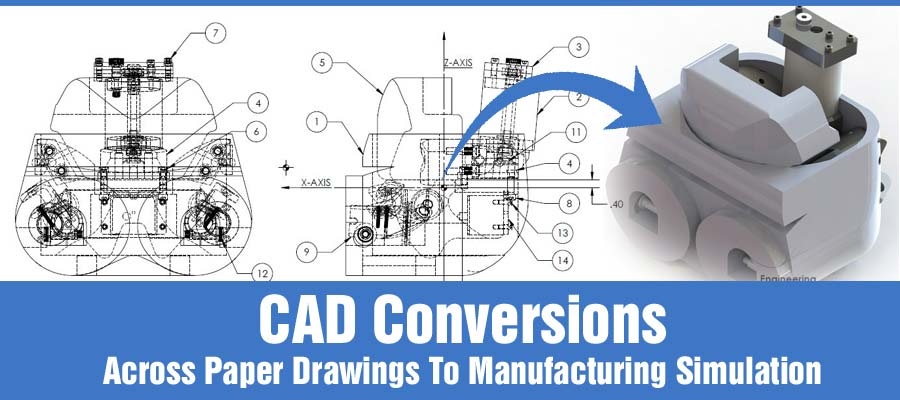
Design engineers and drafters, today, rely upon software for model generation of mechanical components, studying the behavior of component under various physical phenomena, product development, and also for research and development purposes. Even if you have ready 2D drawings for fabrication, it still requires a CAD professional to scan it and/or convert it into 3D CAD solid model.
Moreover, CAD models contain a pool of information associated within them that helps design engineers take critical decisions with prior safety considerations. With several functions and inbuilt features of AutoCAD, SOLIDWORKS, and other modeling software, the process of conversion is a rapid transformation and within the reach of few clicks of mouse.
Apart from inbuilt features of software, another process that design engineers resort to, for quick conversion, is Scan to CAD. It essentially involves conversion of raster scanned images of pdf or paper based hand drawn conceptual sketches to vector drawings. A typical process involves generation of vector drawings for CAD software, which starts with the scanning of a paper based drawing with a high-resolution scanner.
However, the actual process is complicated since it involves multiple accuracy checks, but only with CAD drafters’ expertise it becomes relatively simpler to carry out everyday tasks of any fabrication works out there on the shop floor. On the other hand, with only 2D drafts that were easily understood by designers and drafters, it was still difficult to explain design intent to project stakeholders for large and critical products.
3D CAD models has found its application in several disciplines whether it is fabrication of a machinery component on shop floor, assembling the furniture industry equipment or design structure during construction of large facilities. From blue prints and paper drafts, CAD experts have migrated to 3D models for easy and better understanding, and to print them with 3D printers for enhanced information catalogue.
3D printed and modeled versions holds much more benefits and are informative other than just modeled geometry. The accuracy of such models is far more than what drafters can ever touch. Designs once made are easy to change and update with latest changes and provides the drafter with internal design reviews with increased speed. Owing to such features, product development becomes stronger and relatively speedier since timely developments are incorporated simultaneously.
Furthermore, designs and models of as-built components deliver information related to quantity takeoffs and hence Bill of Materials can be generated for cost estimation. Easy communication with the supplier and stakeholders through such modeled information helps build a level of trust between manufacturers and customers.
In addition to this, the ability of CAD software to have essential checks related to design safety, product development and analysis by virtual model based testing. Other tools of software involves in generating simulation of CNC machining programs by generating prototype and not just a CAD model.
With consistently changing market trends and customer requirements, it becomes quiet difficult for design engineers to alter the designs and start it over from scratch. Simple automatic conversion of 2D drawings to 3D CAD information might sound simple at first go; but when the software encounters intersecting lines or surfaces and hatch patterns, it is bound to make mistakes which can only be solved accurately by a CAD expert.
About Author: Prahlad Parmar is an Engineering Specialist working at Mechanical 3D Modelling for the past 4 years. He caters critical engineering challenges with ease and performs exhaustive procedures to develop robust, well-engineered and high performance designs. He can always be found in the lab discussing, brainstorming and tweaking designs.